5.2.1 Saline aquifers
Froan and Helgeland Basins
The evaluated Jurassic aquifers are located at the Trøndelag Platform, east of the Cretaceous basins which have a green colour in the structural element map. The aquifers are bounded by the subcrop to the Quaternary along the coast to the east, by the Nordland Ridge to the NW and north, and the Frøya High to the SW. The shallow Jurassic aquifers are separated from the Gimsan Basin by large faults and steep slopes. The pore pressure regimes show a general trend transition from high overpressure in the Halten Terrace in the west to hydrostatic pressure towards the Trøndelag Platform in the east. This indicates pressure equilibration across the faulted boundary in geological time. In the Helgeland and Froan Basins, all pore pressures are hydrostatic.
The Åre and Tilje Formations are treated as one aquifer at a regional scale due to the lack of regional sealing shales in the stratigraphy. Both these formations are heterogeneous, with coal beds and shale beds separating channelized sandstones. Internal baffles and barriers at a km scale should be expected, both within the Åre Formation and possibly between Åre and Tilje. Consequently, there is a risk of significant internal barriers within the aquifer and that the communicating volumes may be less than predicted. In the case of low connectivity, a higher number of injection wells than anticipated would be necessary to realize the desired injection volume of CO2.
The Ror Formation is assumed to form a regional seal between the Tilje and Ile formations. The formation often forms a pressure barrier in the fields in the Halten Terrace, and tight shales have been proved in the Ror Fm in wells drilled in the Trøndelag Platform. Laterally, the seal might be broken by large faults.
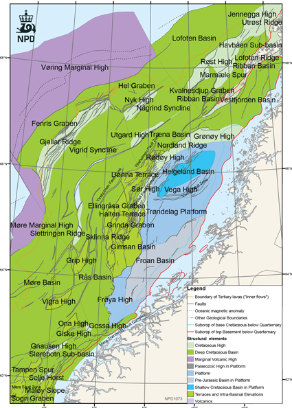
Fig-5-055
Structural element map.
The green area represents basins with thick Cretaceous infill, where Jurassic sediments are generally deeply buried.
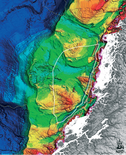
Fig-5-056
Bathymetry map with outlines of the main study area and subcrop lines of Base Cretaceous and the basement. Bathymetry from the Geological Survey of Norway (NGU). Storegga slide to the SW.
The Not Formation is developed as shale in the Trøndelag Platform, and the seismic data indicate a regional distribution. Consequently, it might be expected that the Not Formation will act as a barrier between the Ile and Garn Formations. In the modelling, however, Ile and Garn Formations have been grouped as one aquifer. This simplification was made because of the small volume of the Ile Fm and the existence of faults which could offset the Not Formation and juxtapose Ile with Garn.
The Ile and Garn Formations have very good reservoir properties at the shallow depths encountered in the Trøndelag Platform. The porosity and permeability used in the geomodel are based on the well log data and a few core measurements. The Garn Formation in the Froan Basin is dominated by shallow marine sediments where much better connectivity can be expected than in the tidal-dominated Ile and Tilje Formations. The Ile and Garn formations become more shale-rich towards the Helgeland Basin.
The Rogn Formation in the Draugen area has very good reservoir properties. It is separated from the Garn Formation by shales within the Spekk Formation with variable thickness. It is likely that there will be communication between the Rogn and Garn reservoirs. The Spekk, Melke and Cretaceous shales above the Garn Formation constitute an excellent top seal for the Jurassic aquifers.
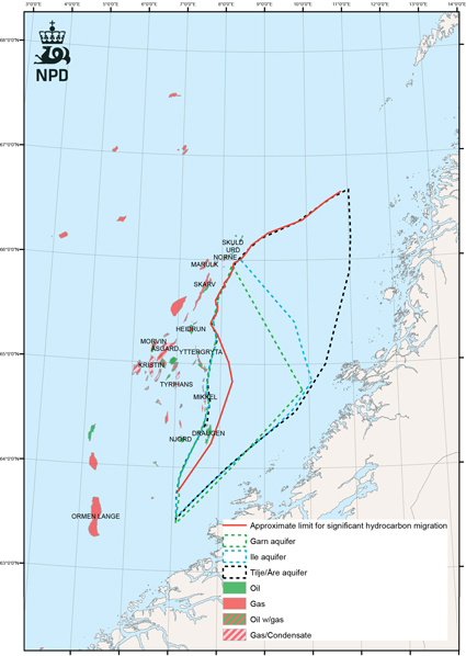
Fig-5-057
Distribution of aquifers in the Trøndelag Platform.
Red line shows the approximate limit for hydrocarbon migration
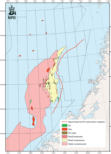
Fig-5-058
Hydrocarbon accumulations and pore pressure regimes in the Jurassic aquifers
Compartmentalization
The northern part of the Trøndelag Platform and the Sør High of the Nordland Ridge are characterized by large graben features such as the Ylvingen Fault Zone and the Ellingråsa Graben. These grabens were probably formed by extension and collapse in the late Jurassic and early Cretaceous. Their size and depth suggest that they could be barriers to fluid flow in the Jurassic aquifers.
In the geomodel, the Ellingråsa Graben is treated as the western boundary of the Jurassic aquifers in the Trøndelag Platform. The Ylvingen Fault Zone could possibly seal off the northern from the southern part of the Åre-Tilje aquifer. Towards the north, in the Grønøy High, the aquifers are truncated by erosion. In the modelling of CO2 injection, the lateral boundaries towards fault structures in the south, west and north are assumed to be closed. Towards the east, aquifers in the Froan Basin terminate at the base of Quaternary sediments below the sea floor. The sealing capacity of the Quaternary sediments along the eastern subcrop is probably low. As shown in the map, the topography of the sea floor is rugged, with basins and ridges carved out by glacial erosion. Comparison with seismic data indicates that the Quaternary cover can be several tens of metres thick in the basins, but much thinner in the slopes. The shallow well 6408/12-U-1 in the Froan Basin has only 6 m Quaternary cover. Most likely, there will be pressure communication between the Jurassic aquifers and the sea water along the subcrop line.
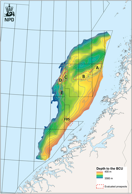
Fig-5-059
Regional BCU map showing the locations of prospects A to E and the location of the simulation grid in the Froan Basin (FBS). The map to the left is zoomed in on structures C, D and E.
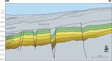
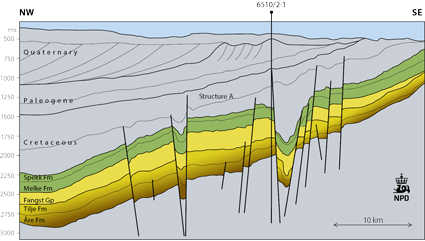
Fig-5-060a - Fig-5-060b
NW – SE profiles across the SE flank of the Helgeland Basin. The closed structures A and B are indicated. The location is shown in The Vestland Group - Hugin Formation.
Froan Basin – long distance CO2 migration
Modeling of CO2 injection and migration in the Froan Basin
The aquifers in the southeastern part of the Norwegian Sea typically have a consistent dip of 1-2 degrees from the Norwegian coast to the basinal areas. In the case of permeable beds occurring along the dip slope, there is a risk that CO2 injected down dip can migrate upwards where the aquifer is truncated by Quaternary glacial sediments. At that depth, CO2 will be in gas phase. The glacial sediments mainly consist of clay and tills, and their thickness ranges from about 10 m to more than 200 m. Understanding the timing and extent of long distance CO2 migration is of importance for evaluation of the storage capacity of outcropping aquifers. Consequently, a modelling study has been conducted on possible aquifers in the Froan Basin.
The Froan Basin is a sub-element of the Trøndelag Platform. It is bound by the Frøya High in the south, the Gimsan Basin and the Halten Terrace in the west, an outcropping basement in the east and the Trøndelag Platform in the north. The Froan Basin was formed by Permian-Early Triassic block faulting. The pre-Jurassic rocks of the Trøndelag Platform were deposited in the NE-SW trending echelon basins. In the early and middle Jurassic, the platform area subsided as one large basin, and the rate of sedimentation was in equilibrium with the rate of subsidence. Consequently, there is a relatively uniform thickness of Jurassic sediments overlying the Triassic and locally the Paleozoic graben infill. Reservoirs which could possibly be used for CO2 injection are the Triassic and Jurassic sandstones. The main seal rocks are the middle to upper Jurassic Melke Fm and Spekk Fm shales as well as the overlying fine grained Cretaceous section. The main risk of leakage is the migration of CO2 towards the Quaternary layer.
Based on simulation results (upscaling of sector model), about 400 mill tons CO2 can be stored in the Garn and Ile aquifer (8 mill tons/year over 50 years). This will require 4 injection wells (2 mill tons/year per well) and yield an acceptable pressure increase (<20bar). After 10,000 years most of the gas will have gone into solution with the formation water or will be residually trapped.
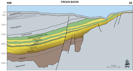
Fig-5-061
NW-SE profile showing the geometry of aquifers (yellow) and sealing formations (green) in the simulation model.
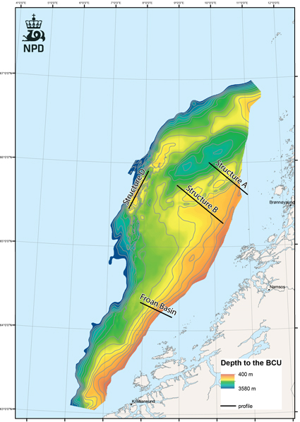
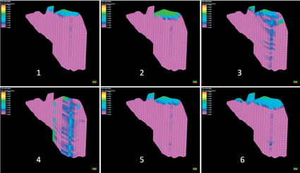
Fig-5-062
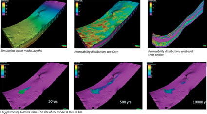
Fig-5-063
The figures in the second row illustrate the free CO2 saturation (green/blue) over 10,000 years.
A simulation sector model of the Garn, Not and Ile Formations was built covering about 10% of the total expected communicating aquifer volume. The top structure (Garn Fm) depth is about 1800 m in the western area and becomes shallower towards the east, with model cut-off at about 500 m depth. The main storage reservoirs are the Garn and Ile Formations with an average permeability of about 400 mD, separated by tight shales within the Not Formation. The Garn Formation consists of three reservoirs, separated by low permeable shale. The porosity and permeability have been stochastically modelled with both areal and vertical variation. The model layers are fine (<1m) at the top reservoir and underneath the shales to capture the vertical CO2 saturation distribution.
The CO2 injection well is located down dip, but alternative locations and injection zones have been simulated, with different injection rates. The injection period is 50 years, and the simulation continues for 10,000 years to verify the long term CO2 migration effects.
The main criteria for evaluation of CO2 storage volumes are the acceptable pressure increase and confinement of CO2 migration (no migration to eastern model boundary within 10,000 years). CO2 will continue to migrate upwards as long as it is in a free movable state. Migration stops when CO2 is permanently bound or trapped, by going into solution with the formation water or by being residually or structurally trapped (mineralogical trapping has not been considered). The trapping achievement of sufficient volumes is depending on a good spreading of the injected CO2. Vertical spreading can to some extent be controlled by injecting into lower reservoir zones, but it is sensitive to vertical permeability and also zonal permeability distribution in the area near the well. Areal spreading can mainly be achieved through use of several injectors.
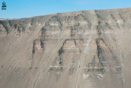
Fig-5-064
Lower Jurassic interbedded sandstones, siltstones and shales belonging to the Neill Klinter Group at Constable Pynt, Jameson Land, East Greenland. The section is about 300 m high. These formations are time equivalent to parts of the Tilje, Tofte, Ror and Ile Formations in the Norwegian Sea, and the depositional environment is similar. Photo: NPD.
The Nordland Ridge aquifer
The Nordland Ridge has three large culminations, the Sør High, the Rødøy High and the Grønøy High. To the west these highs are separated from the petroleum-bearing terraces and basins by large faults. The Sør High is located close to many producing fields, discoveries and prospects. Because some of the gas discoveries, like 6506/6-1 Victoria, have a high CO2 content, it is of interest to identify possible storage sites close to these discoveries where it might be possible to inject excess CO2 from future production.
The Sør High is a structural closure with a culmination at 1000 m below sea level and an area exceeding 500 km2. It is covered by 3D seismic data, and four wells have been drilled. The stratigraphy in the wells is interpreted in the NPD website as a few metres of Fangst Group overlying the Åre Formation. The seismic data show that there is an angular unconformity between the Åre Formation and the thinned Fangst Group. Small amounts of dry methane gas, possibly biogenic, have been encountered. There were no shows indicating heavier hydrocarbons. Due to tilting and block faulting below the unconformity, the Åre Formation has a variable thickness, commonly more than 200 m. The sandstones in the Åre Formation have similar properties as in the Froan Basin. Triassic Grey beds may contribute to the volume of the aquifer.
The Åre aquifer will probably have several local internal baffles and barriers. The top seal will be the overlying Quaternary sediments belonging to the Naust Formation, which has a minimum thickness of about 650 m. The sediments in the Naust Formation are unfaulted and consist of silt and clay. The geological setting of this top seal is analogous to the Utsira Formation in the Sleipner area. The small accumulations of methane gas in the Sør High show that the Naust Formation has a sealing capacity. Further maturation of the Sør High as an injection site for CO2 would require a better quantification of the Naust sealing capacity.
Møre Margin
The Møre Margin south of the Frøya High is separated from the Froan Basin by the Jan Mayen Fracture Zone lineament. Its Mesozoic and Cenozoic geology is very different from the Trøndelag Platform. Along the Møre Margin, a thin Jurassic and thick Cretaceous section dip towards the deep Møre Basin. In this setting of regionally dipping strata, only a few closed structures of small sizes exist. The Jurassic reservoir sands tend to be thin, and no Cretaceous reservoir of interest has so far been proved by drilling. A few exploration wells drilled in the area have proved that gas has migrated into closed structures close to the coast. A possible storage option in the Møre Margin is thought to be the Paleocene submarine fans of the Egga sandstone, which constitute the reservoir of the Ormen Lange Field. This sand was derived from the Møre Paleogene highlands and has not been encountered in the Froan and Helgeland Basins. A limited Jurassic storage potential could exist in a narrow zone close to the coast. Both the Egga sandstone and the Jurassic aquifers subcrop towards a thin Quaternary section below the sea floor. CO2 migration to the subcrop area and leakage to the sea is the most obvious risk for these aquifers. No closed structures suitable for CO2 injection have been identified in the Møre Margin.
Ellingråsa Graben
The dry exploration well 6507/12-1 was drilled near the culmination of a large closed structure in the southern part of the Ellingråsa Graben. The well penetrated the Åre-Tilje, Ile and Garn aquifers between 2100 and 2900 m depths below sea level. The structure is within the area of possible hydrocarbon migration. Since this well was dry and no shows were reported, it is very unlikely that hydrocarbons can have migrated further into the Ellingråsa Graben. The 6507/12-1 structure has been assessed as a possible target for CO2 injection. The storage efficiency depends on communication with the aquifers in the Halten Terrace and the producing Midgard gas field to the west. The calculation of the storage volume within the structure is based on a closure of 200 m and storage in all aquifers with a storage efficiency of 10%. Maturation of this prospect should include an evaluation of the communication with the Halten Terrace, Nordland Ridge and Trøndelag Platform. The 3D seismic data show that the Jurassic aquifers are strongly faulted, with the risk that the reservoir might be divided in many compartments. The faults do not appear to offset the Upper Jurassic and Lower Cretaceous sealing shales.
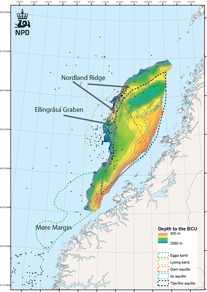
Fig-5-065
Simulation model of the The Nordland Ridge Structure D
The simulation model of the Nordland Ridge Structure D was built for the purpose of assessing its CO2 storage potential within the Åre Formation (Rhaetian-Pliensbachian, Lower Jurassic). The modelled Structure D is a closed structure with CO2 storage potential in two structural domes.
Segment 3 is the deepest dome, and segments 1 and 2 combined represent the shallowest dome. There is a possibility for down flank aquifer communication to areas outside of the model.
The depth of the top reservoir (Åre Formation) in two main storage domes is between 1000 m and 1150 m. Generally the thickness of the Åre Fm varies between 300 and 500 m, with a maximum thickness of 780 m in the eastern part of the Halten Terrace (Heidrun area).
The Åre Formation consists of heterogeneous fluvial deposited sand channels with an uncertain communication. The average sand permeability is about 500 mD. The porosity and permeability have been stochastically modelled with both lateral and vertical variation. The CO2 injection well is located down dip, at the apex of the two deepest main storage domes (segment 3).
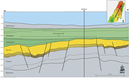
Fig-5-066
SW-NE profile showing the geomery of aquifer (yellow) and sealing formations (green) in the simulation model. The location is shown here.
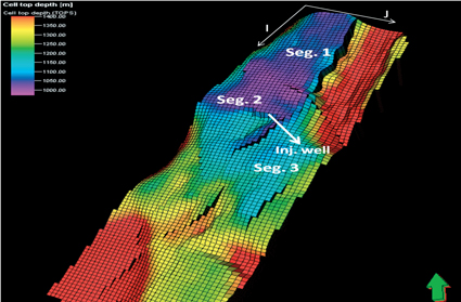
Fig-5-067
Simulation model depth, top Åre Fm.
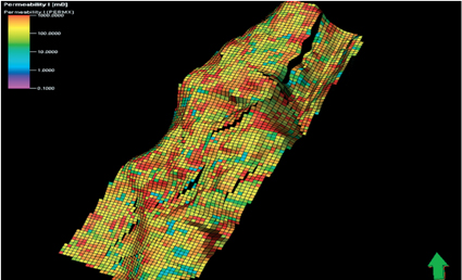
Fig-5-068
Lateral permeability variations.
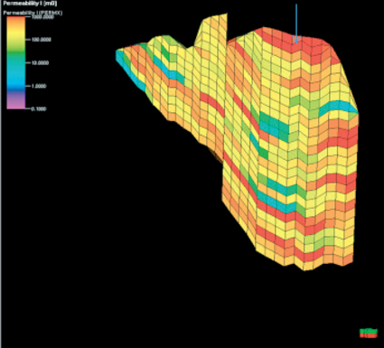
Fig-5-069
Vertical permeability variations (x-z, through well).
Different injection rates and volumes have been simulated. The figures above illustrate CO2 saturation (green/blue) over 50 and 1000 years. The main simulation case injects 2 mill SM3 CO2/day (daily rate of 1/5000 of total volume) for 28 years with acceptable pressure increase and CO2 plume spreading. CO2 will continue to migrate upwards as long as it is in a free movable state.
Migration ends when CO2 is permanently bounded or trapped, by going into solution with the formation water or by being residually trapped (mineralogical trapping has not been considered).
Structural trapping is the main storage mechanism in the simulation model of the Nordland Ridge.
Applying a safety factor of 2 to the acceptable pressure increase, shows that 18.7 Mt of CO2 can safely be stored in the Nordland Ridge within the Åre Formation.
Simulation Cases:
- Geological model and properties.
- Zero transmissibility (communication) across modelled faults. Most faults are not extensive and do not fully close off model communication. The degree of communication across faults is uncertain.
- Zero transmissibility (communication) between model layers. Reflects that well logs show sand/shale sequence in individual model layers, but zero vertical communication is an extreme case, since the sand/shale sequences are not extensive. Vertical communication still goes on through “zig-zag” vertical communication via faults.
- Combines Case 2 & 3 above.
- Case with no CO2 going into solution with water. Not expected to have significant effect when main storage mechanism is structural trapping.
- Increased model pore volume by multiplying the pore volume of the boundary grid cells. Total model pore volume increases from 27 GSm3 to 100 GSm3, reflecting possible communicating pore volume. Injects 2.5 times the rates and volumes of the Case 1.
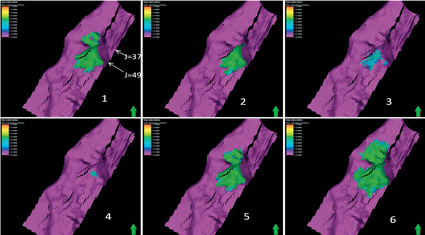
Fig-5-070
CO2 plume top reservoir end of injection (50 yrs)
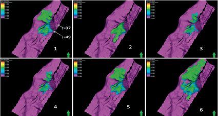
Fig-5-071
CO2 plume top reservoir after 1000 yrs.
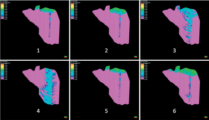
Fig-5-072
CO2 plume x-z cross section (J=49) end of injection (50 yrs).